

Pump and motor flange and shaft dimensions
Excerpts from the SAE J744C (ANSI) standard for hydraulic pump and motor mounting flanges and shafts. Dimensions in millimetres and inches.
2-bolt flange
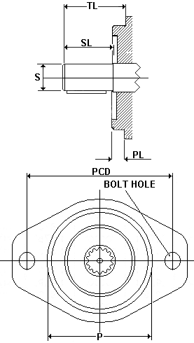
| SAE-koodi | Pilot ø | Bolt circle (PCD) | Bolt hole | Pilot (PL) |
|---|---|---|---|---|
| AA | 50,8 2,00″ | 82,55 3,250″ | 10,31 0,406″ | 6,35 0,250″ |
| A | 82,55 3,25″ | 106,35 4,187″ | 11,10 0,437″ | 6,35 0,250″ |
| B | 101,6 4,00″ | 146,05 5,750″ | 14,27 0,562″ | 9,53 0,375″ |
| C | 127,0 5,00″ | 180,98 7,125″ | 17,45 0,687″ | 12,7 0,500″ |
| D | 152,4 6,00″ | 228,6 9,000″ | 20,62 0,812″ | 12,7 0,500″ |
| E | 165,1 6,50″ | 317,5 12,500″ | 26,97 1,062″ | 15,88 0,625″ |
| F | 177,8 7,00″ | 350,04 13,781″ | 26,97 1,062″ | 15,88 0,625″ |
Dimensions in mm, inch value in small print. Markings in the drawing: PCD = bolt circle diameter, PL = pilot length.
4-bolt flange
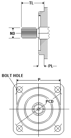
| SAE-koodi | Pilot ø | Bolt circle (PCD) | Bolt hole | Pilot (PL) |
|---|---|---|---|---|
| B | 101,6 4,00″ | 127,0 5,000″ | 14,27 0,562″ | 9,53 0,375″ |
| C | 127,0 5,00″ | 161,93 6,375″ | 14,27 0,562″ | 12,7 0,500″ |
| D | 152,4 6,00″ | 228,6 9,000″ | 20,62 0,812″ | 12,7 0,500″ |
| E | 165,1 6,50″ | 317,5 12,500″ | 20,62 0,812″ | 15,88 0,625″ |
| F | 177,8 7,00″ | 350,04 13,781″ | 26,97 1,062″ | 15,88 0,625″ |
4-bolt flanges are typically used on larger units (frame size B and up).
Straight keyed shafts
| SAE-koodi | Shaft ø (S) | SL | TL | Key width |
|---|---|---|---|---|
| AA | 12,7 1/2″ | 19,05 0,750″ | 26,97 1,062″ | 3,18 0,125″ |
| A | 15,88 5/8″ | 23,80 0,937″ | 31,75 1,250″ | 3,96 0,156″ |
| B | 22,23 7/8″ | 33,38 1,3142″ | 41,28 1,625″ | 6,35 0,250″ |
| BB | 25,4 1″ | 38,1 1,500″ | 46,02 1,812″ | 6,35 0,250″ |
| C | 31,75 1 1/4″ | 47,63 1,875″ | 55,55 2,187″ | 7,92 0,312″ |
| CC | 38,1 1 1/2″ | 53,98 2,125″ | 61,90 2,437″ | 9,53 0,375″ |
| D | 44,45 1 3/4″ | 66,68 2,625″ | 74,60 2,937″ | 11,10 0,437″ |
S = shaft diameter, SL and TL = length dimensions as in the 2-bolt flange drawing. The table lists the common short shaft types – for long series, see SAE J744C.
Splined shafts (spline, 30° evolventti)
| SAE-koodi | Spline | Nominal ø (ND) | TL |
|---|---|---|---|
| AA | 9T 20/40DP | 12,7 1/2″ | 26,97 1,062″ |
| A | 9T 16/32DP | 15,88 5/8″ | 31,75 1,250″ |
| AH | 11T 16/32DP | 19,05 3/4″ | 31,75 1,250″ |
| B | 13T 16/32DP | 22,23 7/8″ | 41,28 1,625″ |
| BB | 15T 16/32DP | 25,4 1″ | 46,02 1,812″ |
| C | 14T 12/24DP | 31,75 1 1/4″ | 55,55 2,187″ |
| CC | 17T 12/24DP | 38,1 1 1/2″ | 61,90 2,437″ |
| D | 13T 8/16DP | 44,45 1 3/4″ | 74,60 2,937″ |
| E | 13T 8/16DP | 44,45 1 3/4″ | 74,60 2,937″ |
| F | 15T 8/16DP | 50,8 2″ | 87,30 3,437″ |
T = number of teeth, DP = diametral pitch. ND and TL = as in the 4-bolt flange drawing.
Source: excerpts from the SAE J744C (ANSI) standard. We are happy to help with identification.
The calculators and tables on this page are indicative aids only. They are based on general theoretical formulas and typical tabulated values, and do not account for all real-system conditions such as losses, temperatures, tolerances, material differences or component condition and wear. The results must not be used as the sole basis for dimensioning, manufacturing or safety; always verify dimensioning and suitability against the component manufacturer's official technical data and the applicable standards and regulations. PV-Hydrauli Oy accepts no liability for possible errors in this information or for any direct or indirect damage arising from its use. If in doubt, we are happy to help – Contact.