

Gear pump rotation direction
A gear pump running in the wrong direction delivers no oil, because the suction and pressure sides swap places – and the pump may also be damaged. This page shows how to identify the rotation direction and how to reverse it when necessary.
How to identify the direction of rotation
- Always look at the pump from the drive shaft end, with the shaft pointing towards you.
- If the suction port is on the left, the pump rotates clockwise. If the suction port is on the right, the pump rotates counter-clockwise.
- The suction port is usually larger than the pressure port, so the sides are easy to identify from the port sizes.
- Many manufacturers mark the housing with an arrow showing the oil flow or rotation direction. The type designation also often indicates the direction – marking conventions vary by manufacturer, so check the manufacturer's table.
- The direction can also be deduced from the drive: when you look at the drive (e.g. an electric motor or PTO) from its shaft end, the pump's rotation direction is the opposite – the two are viewed from opposite directions.
- Identification is further helped by the name plate data, displacement measurement and flange and shaft dimensions.
Reversing the direction of rotation
Not all gear pumps are reversible.
Sometimes the rotation direction of a gear pump needs to be reversed. It is important to note, however, that not all gear pumps are reversible. Some pumps are one-directional by design, and their rotation cannot be reversed without a risk of damage.
Before dismantling the pump or starting any modification work, always check the manufacturer's instructions to confirm whether the pump model is reversible and what the correct reversal procedure is.
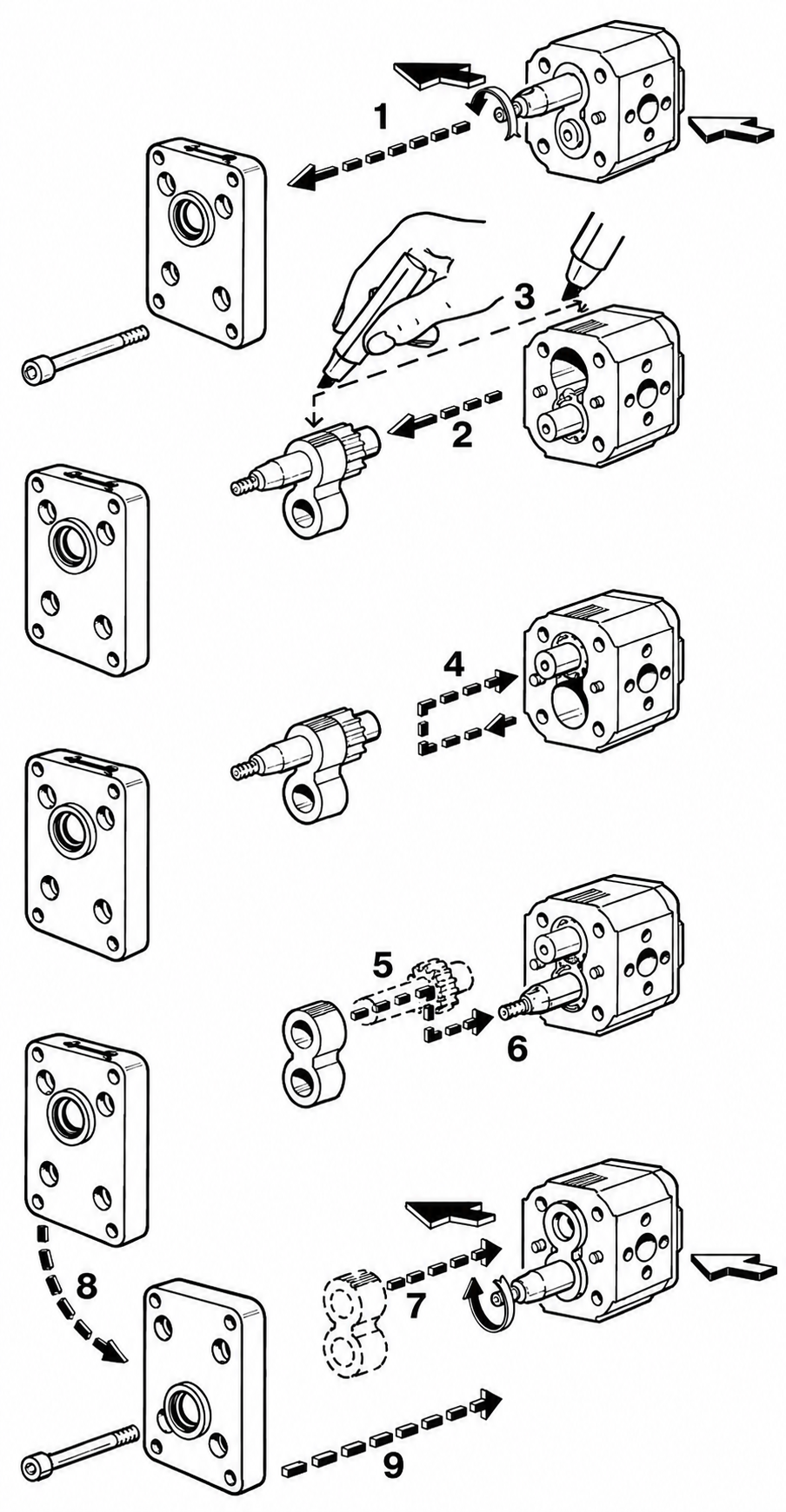
The instructions below are an example for one common external gear pump construction and do not apply to all pumps as such. The direction is reversed by turning the internal parts around, following the numbering in the picture:
- Remove the end cover bolts and lift off the cover.
- Carefully pull the shaft, gears and bearing brackets out of the housing.
- Mark the relative position of the parts, e.g. with a marker pen, before dismantling.
- Remove the gears and shaft from the bearing brackets.
- Turn the bearing brackets through 180 degrees.
- Refit the shaft and gears into the brackets.
- Push the assembly back into the housing.
- Turn the end cover through 180 degrees as well.
- Refit the cover and tighten the bolts to the manufacturer's specified torque.
Maintain absolute cleanliness during dismantling and assembly. If seals are damaged during fitting they must be replaced – also make sure the seals are not pinched. Observe the housing bolt tightening torques.
Remember that after the reversal the old direction arrow and type designation on the housing no longer apply – mark the new direction on the pump.
The calculators and tables on this page are indicative aids only. They are based on general theoretical formulas and typical tabulated values, and do not account for all real-system conditions such as losses, temperatures, tolerances, material differences or component condition and wear. The results must not be used as the sole basis for dimensioning, manufacturing or safety; always verify dimensioning and suitability against the component manufacturer's official technical data and the applicable standards and regulations. PV-Hydrauli Oy accepts no liability for possible errors in this information or for any direct or indirect damage arising from its use. If in doubt, we are happy to help – Contact.